Welcome to Software Development on Codidact!
Will you help us build our independent community of developers helping developers? We're small and trying to grow. We welcome questions about all aspects of software development, from design to code to QA and more. Got questions? Got answers? Got code you'd like someone to review? Please join us.
Post History
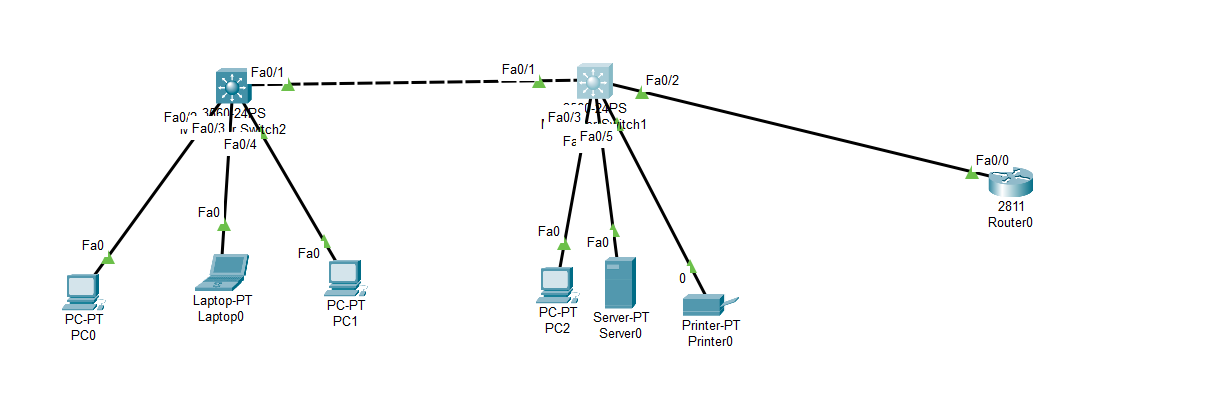
I have created a simple bus topology connecting 2 switches and a router, with each switch connected to their respective end devices through ordinary star topology. The switch model used was 3560-24...
#2: Post edited
I have created a simple bus topology connecting 2 switches and a router, with each switch connected to their respective end devices through ordinary star topology. The switch model used was **3560-24PS** and the router's being **2811**.- 
- 1. I have created a VLAN for each switch and assigned the interfaces connected to the end devices to the same VLAN, to form a subnet. Namely, Switch 1 end devices are part of VLAN 10 and Switch 2 devices part of VLAN 20.
- 
- 
- 2. Next, I configured the interfaces of each switch that is connected to each other, and the interface of switch 2 which is connected to the router to be trunk ports, and enabled traffic for both VLANs.
- 
- 
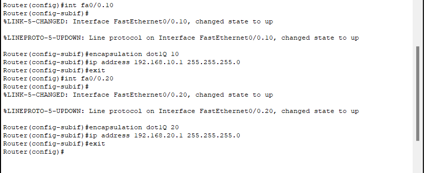
- 3. Then, I configured inter-VLAN routing in the router by configuring the router port interface connected to Switch 3 with 2 subinterfaces for each VLAN to act as each's default gateway.
- 
- 4. Finally, I configured each end device of both VLANs with static IPs and their respective default gateways. The default gateway of devices of VLAN 10 are configured with the IP of its router subinterface: 192.168.10.1 and VLAN 20: 192.168.20.1
Nevertheless, when attempting to send a simple PDU between a device in VLAN 10 to a device in VLAN 20, it shows "Failed". I tried pinging too using the command prompt. Why is this the case? Is there something that I am missing or overlooking? I have been extensively looking up resources online for days and cracking my skull,and tried different steps but to no avail. Please do help me as I need to figure this out to successfully carry out inter-VLAN communication for my networking module assignment for university which is a lot more complex than this simple example.Please find attached the packet tracer file for this example:- [Packet Tracer File](https://drive.google.com/file/d/1jeg2xJafPH5IFZfHsDmp-eJaiJM3XeA7/view?usp=sharing)
- Thank you very much in advance! :)
P.S Hopefully this question will be allowed here on this Codidact site. Please do not remove it as I really need answers to this question to which Stack Exchange have closed many times because it "lacked clarity" and other poor reasons. What more clarity do you need?! It's frankly quite sickening how it operates-most of my IT questions were closed. I hope Codidact is better.
- I have created a simple bus topology connecting 2 switches and a router, with each switch connected to their respective end devices through ordinary star topology. The switch model used was **3560-24PS** and the router's was **2811**.
- 
- 1. I have created a VLAN for each switch and assigned the interfaces connected to the end devices to the same VLAN, to form a subnet. Namely, Switch 1 end devices are part of VLAN 10 and Switch 2 devices part of VLAN 20.
- 
- 
- 2. Next, I configured the interfaces of each switch that is connected to each other, and the interface of switch 2 which is connected to the router to be trunk ports, and enabled traffic for both VLANs.
- 
- 
- 3. Then, I configured inter-VLAN routing in the router by configuring the router port interface connected to Switch 3 with 2 subinterfaces for each VLAN to act as each's default gateway.
- 
- 4. Finally, I configured each end device of both VLANs with static IPs and their respective default gateways. The default gateway of devices of VLAN 10 are configured with the IP of its router subinterface: 192.168.10.1 and VLAN 20: 192.168.20.1
- Nevertheless, when attempting to send a simple PDU between a device in VLAN 10 to a device in VLAN 20, it shows "Failed". I tried pinging too using the command prompt. Why is this the case? Is there something that I am missing or overlooking? I have been extensively looking up resources online for days and cracking my skull, and tried different steps but to no avail. Please do help me as I need to figure this out to successfully carry out inter-VLAN communication for my networking module assignment for university which is a lot more complex than this simple example.
- I am attaching the packet tracer file for this example:
- [Packet Tracer File](https://drive.google.com/file/d/1jeg2xJafPH5IFZfHsDmp-eJaiJM3XeA7/view?usp=sharing)
- Thank you very much in advance! :)
#1: Initial revision
Why is inter-VLAN communication not working in my bus topology network set-up in Cisco Packet Tracer?
I have created a simple bus topology connecting 2 switches and a router, with each switch connected to their respective end devices through ordinary star topology. The switch model used was **3560-24PS** and the router's being **2811**.  1. I have created a VLAN for each switch and assigned the interfaces connected to the end devices to the same VLAN, to form a subnet. Namely, Switch 1 end devices are part of VLAN 10 and Switch 2 devices part of VLAN 20.   2. Next, I configured the interfaces of each switch that is connected to each other, and the interface of switch 2 which is connected to the router to be trunk ports, and enabled traffic for both VLANs.   3. Then, I configured inter-VLAN routing in the router by configuring the router port interface connected to Switch 3 with 2 subinterfaces for each VLAN to act as each's default gateway.  4. Finally, I configured each end device of both VLANs with static IPs and their respective default gateways. The default gateway of devices of VLAN 10 are configured with the IP of its router subinterface: 192.168.10.1 and VLAN 20: 192.168.20.1 Nevertheless, when attempting to send a simple PDU between a device in VLAN 10 to a device in VLAN 20, it shows "Failed". I tried pinging too using the command prompt. Why is this the case? Is there something that I am missing or overlooking? I have been extensively looking up resources online for days and cracking my skull,and tried different steps but to no avail. Please do help me as I need to figure this out to successfully carry out inter-VLAN communication for my networking module assignment for university which is a lot more complex than this simple example. Please find attached the packet tracer file for this example: [Packet Tracer File](https://drive.google.com/file/d/1jeg2xJafPH5IFZfHsDmp-eJaiJM3XeA7/view?usp=sharing) Thank you very much in advance! :) P.S Hopefully this question will be allowed here on this Codidact site. Please do not remove it as I really need answers to this question to which Stack Exchange have closed many times because it "lacked clarity" and other poor reasons. What more clarity do you need?! It's frankly quite sickening how it operates-most of my IT questions were closed. I hope Codidact is better.


